If you’ve ever spent time sourcing diodes for circuit design, you’ve probably asked this question: Why does reverse resistance matter so much? For someone on the supply side of semiconductors, I can tell you it’s not just a technical detail—it’s one of the first things I discuss with engineers when they reach out for samples. Let’s break down how reverse resistance shifts with voltage, why it matters for your projects, and what you should look for when choosing a diode. DIODE

First, let’s get the basics straight: reverse resistance is a diode’s opposition to current flowing in the reverse direction—the one where the anode is more negative than the cathode. Unlike forward resistance, which is low (meant to let current pass easily), reverse resistance is supposed to be very high. That’s the whole point: when a diode is reverse biased, it blocks current. But here’s where it gets tricky: it’s not a fixed number. It changes depending on how much reverse voltage you apply, and that change isn’t linear. As a diode supplier, I see this play out every day in design decisions—too many engineers treat reverse resistance as a static value, and that leads to headaches later.
Let’s start with the physics to make sense of it. A diode is a PN junction, right? The P-side has holes (positive charge carriers) and the N-side has electrons (negative charge carriers). When you apply a reverse voltage, you’re pulling holes away from the junction and pushing electrons away from it. That creates a depletion region—a thin layer near the junction with no free charge carriers. The width of this depletion region is key here: as reverse voltage increases, the electric field across the junction gets stronger, which pulls more charge carriers out of the region, making the depletion layer wider.
Now, reverse resistance is essentially the total opposition to current in reverse bias. There are two tiny currents that flow in reverse, even when everything is working as it should: leakage current and saturation current. Leakage current is the small amount of charge that still slips through the depletion region, and it’s tied directly to the depletion region’s width. Here’s the link to reverse resistance: if leakage current is low, reverse resistance is high. If leakage current goes up, reverse resistance goes down. And as reverse voltage changes, that relationship flips.
At low reverse voltages—think less than 10% of the diode’s rated reverse breakdown voltage—reverse resistance is very high, almost constant. Why? Because the depletion region is still thin enough that leakage current is barely changing. The electric field is strong enough to keep most carriers separated, so only a tiny number make their way through. For example, take a 1N4001 diode, which has a rated reverse voltage of 50V. At 5V reverse bias, its reverse resistance is around 100MΩ. That’s a solid high resistance—perfect for blocking current.
But here’s the part that trips people up: once you pass that initial low-voltage range, reverse resistance starts to drop as reverse voltage increases. Wait, why? Because the wider depletion region creates more surface area where impurities in the semiconductor can trap charge carriers. Those trapped charges act like tiny paths for current, so leakage current goes up. Since reverse resistance is voltage divided by current (Ohm’s Law, R = V/I), if current rises faster than voltage, resistance decreases. Let’s use that same 1N4001 example: at 25V reverse bias (half its rated voltage), reverse resistance is around 40MΩ—cut by more than half. At 45V, just below breakdown, it drops to 5MΩ. That’s a huge shift, and it’s not just a number you can ignore.
Then there’s the breakdown region. When reverse voltage hits the diode’s rated maximum, two things can happen: Zener breakdown or avalanche breakdown. In Zener diodes, this is a controlled effect where reverse resistance drops sharply but remains consistent, which is why they’re used for voltage regulation. For regular rectifier diodes, though, breakdown is a failure mode. Reverse resistance plummets to nearly zero, and current spikes—if you don’t limit that current, the diode burns out. As a supplier, I always warn engineers: never operate a diode near its breakdown voltage unless it’s a Zener. We’ve sent out samples that worked great at 80% of rated reverse voltage, only for customers to have them fail because they pushed it to 100% without current limiting.
Now, why does this matter for your projects? If you’re designing a power supply, for example, the rectifier diodes need high reverse resistance at their rated operating voltage to prevent backflow from the output side. If reverse resistance drops too much, you get leakage current that wastes power, overheats components, or even causes voltage spikes. We had a customer last year who was building a 12V power supply and used a diode with a reverse resistance that dropped too much at their operating voltage—their supply was drawing 10% more idle current than expected, and their battery life was shorter. They switched to a higher-quality diode from our line with a steeper reverse resistance curve, and the issue was fixed instantly.
Another example: automotive electronics, where diodes are used to protect circuits from voltage spikes. A car’s alternor can send transient reverse voltage up to 60V, so the diode needs consistent reverse resistance across that range. If the reverse resistance drops at high voltage, the protection diode won’t block the spike, and the main circuit gets damaged. We’ve worked with several automotive teams to test our diodes under actual operating conditions, and we adjust our specifications to make sure reverse resistance stays stable from low to mid-range reverse voltages, not just at the low end.
You might be wondering: is there a way to predict how reverse resistance will change for a specific diode? It depends on the diode’s material, size, and manufacturing process. Silicon diodes, which are the most common, have a reverse resistance curve that drops gradually as voltage increases, while Schottky diodes have lower reverse resistance overall—because their depletion region is thinner. Schottkys are used in high-speed switching applications where forward voltage drop is more important than maximum reverse resistance, which is a tradeoff engineers have to weigh. As a supplier, I make sure to label each diode’s reverse resistance vs. voltage curve clearly, and we include test data in every datasheet so engineers don’t have to guess.
A common mistake I see is using the reverse resistance value at 0V or a very low voltage as the “real” value. Let’s say an engineer picks a diode with a 100MΩ reverse resistance at 1V, but their circuit operates at 20V. At that higher voltage, the diode’s reverse resistance might be only 20MΩ—so the leakage current is 5x higher than they expected. That tiny detail can cause big problems. That’s why I always advise customers to look at the curve, not just the single number. If you send us your circuit’s operating voltage, we can point you to the diode in our line that maintains the highest reverse resistance across your operating range, and even send free samples for testing.
What about temperature? Oh, right—temperature plays a role too. As the diode gets hotter, the charge carriers in the depletion region move faster, so more of them slip through, increasing leakage current and lowering reverse resistance. A diode that has a 40MΩ reverse resistance at 25°C might drop to 10MΩ at 100°C. That’s critical for industrial applications, where devices run hot. We test all our diodes at different temperatures, and our datasheets include reverse resistance values at -40°C, 25°C, and 125°C, so engineers can see how it performs in harsh environments.
So to circle back to the original question: reverse resistance doesn’t change randomly—it follows a predictable curve tied to reverse voltage, material, and temperature. It’s high and stable at low reverse voltages, decreases gradually as voltage approaches rated values, and plummets near breakdown. For diode users, understanding that curve is the difference between a circuit that works and one that fails. For suppliers like me, it’s our job to make sure our diodes are manufactured to have the reverse resistance characteristics you need, and to give you the data to make the right choice.
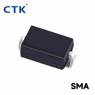
If you’re working on a project and need to confirm how a specific diode’s reverse resistance will behave, or if you’re not sure which diode is right for your voltage requirements, don’t hesitate to reach out. We have engineers who can walk you through the data, send samples for testing, and help you find the perfect fit for your design.
Switching Diode References
- Sze, S. M. (1981). Physics of Semiconductor Devices. John Wiley & Sons.
- Neamen, D. A. (2003). Semiconductor Physics and Devices: Basic Principles. McGraw-Hill.
- Bilotti, F., & Vegni, L. (2009). Semiconductor Devices for High-Speed Applications. Artech House.
- Company internal diode testing standards, 2024.
Tongke Electronic Co., Ltd
Tongke Electronic Co., Ltd. is one of the most experienced diode manufacturers and suppliers in China, featured by quality products and low price. Please rest assured to wholesale advanced diode made in China here from our factory. Contact us for pricelist.
Address: No.3,Chayuan Rd, Street 3, AilingKan, Dalingshan, Dongguan, Guangdong, China.
E-mail: jack@ctk-elec.com
WebSite: https://www.ctkchip.com/
